
[Training a 500B LLM from Scratch] 12/25: How Do We Install the NICs and Cables for 5,120 GPUs?
The previous article put machines, power, and cooling on one facility plan. The three halls are connected on paper. Behind a real cabinet, however, that line has to answer a more concrete question: which port takes the fiber in my hand, and where does its other end go?
I start with one server's wiring sheet. The eight-GPU B200 system, ConnectX-7 NICs, 400G InfiniBand switches, optics, and fibers retain Part 3's choices. Connect one outlet first, identify every part, then extend the rule to a cabinet, a group, and three halls. Installation staff can then match records to equipment, and the next person can reconnect the same cable during maintenance.
Where Does the Other End of This Cable Go?
Before touching the first cable, find its destination on the overview. Hall A holds pods 1 and 2, Hall B pods 3 and 4, and Hall C pod 5 and the core. A pod groups servers on the network. Results from a machine in Hall A can reach one in Hall B along this route:
Server → leaf → local aggregation → core → destination aggregation → leaf → server.
Leaves sit next to the servers, aggregation joins the leaves within a group, and the core joins groups. Machines on different leaves in the same pod can turn at local aggregation; crossing pods requires the core. Every arrow below must become optics and fiber. I start at the server and give each section a physical connection.
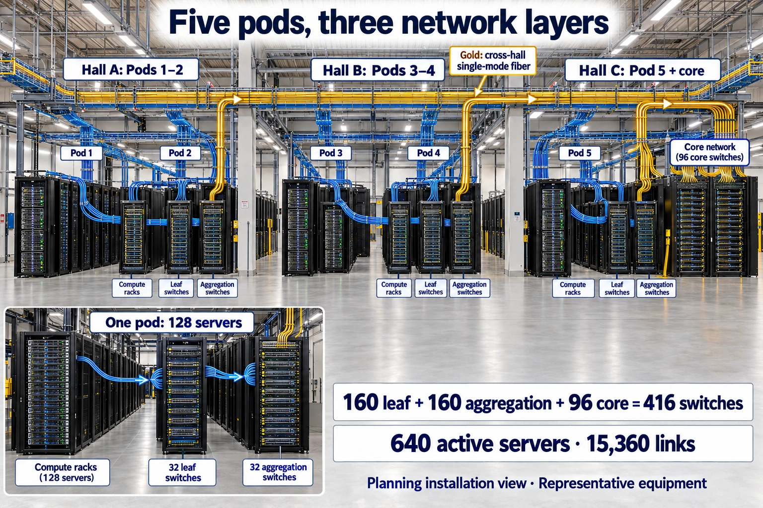
Representative cabinets and cable trays show the physical installation layers. Read complete quantities from the labels and cable schedule. Click to open the full image.
Which Connections Arrive Assembled, and Which Are Installed Here?
Open the delivery list and establish what is arriving. B200 names the GPU. The order buys an Exxact system containing eight of them, with processors, memory, power supplies, fans, and expansion slots inside a rack-mount chassis.
Those eight GPUs also exchange results, but their connections are inside the machine. The HGX B200 platform uses NVLink and NVSwitch, assembled and validated by the system supplier before delivery. The site accepts that system first, then connects its external network. That establishes the installation boundary.
NVLink: A high-speed interconnect between GPUs. In this article, it connects GPUs inside one server.
NVSwitch: A switching component that connects multiple GPUs inside a server.
Check the order again for the external outlets. Part 3 assigns eight single-port ConnectX-7 NICs to each server, part MCX75310AAS-NEAT. Cards, slots, optics, and tests go into the integrated server order together. On arrival, all eight training outlets are checked against it.
NIC: A network interface card installed in a server to connect it to an external network.
On-site NIC installation also has a defined procedure: qualified staff follow the system manual, disconnect every redundant feed, take precautions against electrostatic discharge, then install the cards. With that work assigned correctly, the wiring sheet continues to identify each installed card and its destination.
Walk behind the chassis and find the training NIC ports
Behind the chassis, connectors crowd between fans and power supplies. Shape alone is easy to misread. Mark the rear-panel regions first so every training cable has an identified starting point.
Exxact's public full rear-panel view is not sufficiently clear. I use the official manual for another 8U B200 system, the ASRock 8U8X-TURIN2 SYN B200, to establish the component relationships. Procurement remains Exxact, with actual slots mapped individually to its delivery drawing.
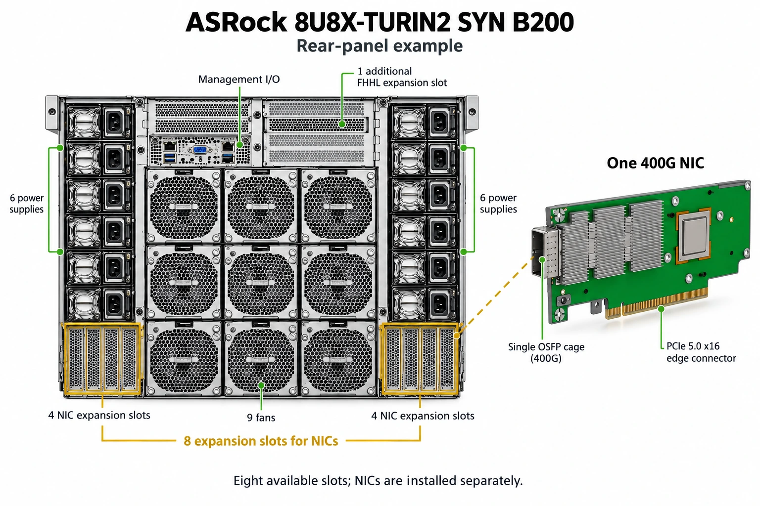
Structural reference based on the ASRock manual; the project's procurement model remains Exxact. Click to view the original image.
On this ASRock panel, supplies sit on both sides, fans in the middle, management connectors above, and four expansion positions at the bottom of each side. A NIC's edge connector meets the internal PCIe connection, while its bracket is secured in the chassis opening. Its network port is then exposed at the rear. An empty slot is only a position; the delivery list establishes whether a card occupies it.
PCIe expansion slot: A position inside a server for an expansion card such as a NIC. Once the card is installed, its external connector usually becomes accessible through a chassis bracket.
The wiring sheet separates management from training. Management ports provide status and remote control; training ports carry large GPU data exchanges. Recording their networks separately prevents a familiar management connector from becoming a mistaken training outlet.
Label the eight training NICs NIC1 through NIC8, map each to its real slot, then record the card identifier. These numbers are project labels. Counting from the chassis's left edge is not enough: the manufacturer's slot and project number must match in the record.
One NIC, one transceiver, one fiber cable: make the first connection
Following the sheet, I reach P1-S01, the first server in the first group, and stop at NIC1. Its single-port 400G card exposes an OSFP cage. Insert the MMA4Z00-NS400 module, then fit matching multimode fiber into the module's MPO-12/APC connector. The assembly has three levels: card in server, module in card, fiber in module.
Optical transceiver: A component that converts electrical signals into optical signals and receives optical signals. It plugs into the equipment, and the fiber cable plugs into it.
MPO: A connector that combines multiple optical fibers in one plug. This plan uses the specified MPO-12/APC type.
400G: Here, a nominal transmission rate of 400 billion bits per second for each network link.
The other end reaches the switch. The selected NVIDIA Quantum-2 MQM9700-NS2F has 32 OSFP cages. Each dual-port MMA4Z00-NS module supplies two independent 400G connections. That is how the 64 logical ports on the parts list emerge from 32 modules.
OSFP: The form factor used for the transceivers and cages in this article. A transceiver must also match the network type, speed, and distance requirements.
Logical port: An independently used network connection endpoint. Here, a dual-port transceiver in one switch cage provides two such endpoints.
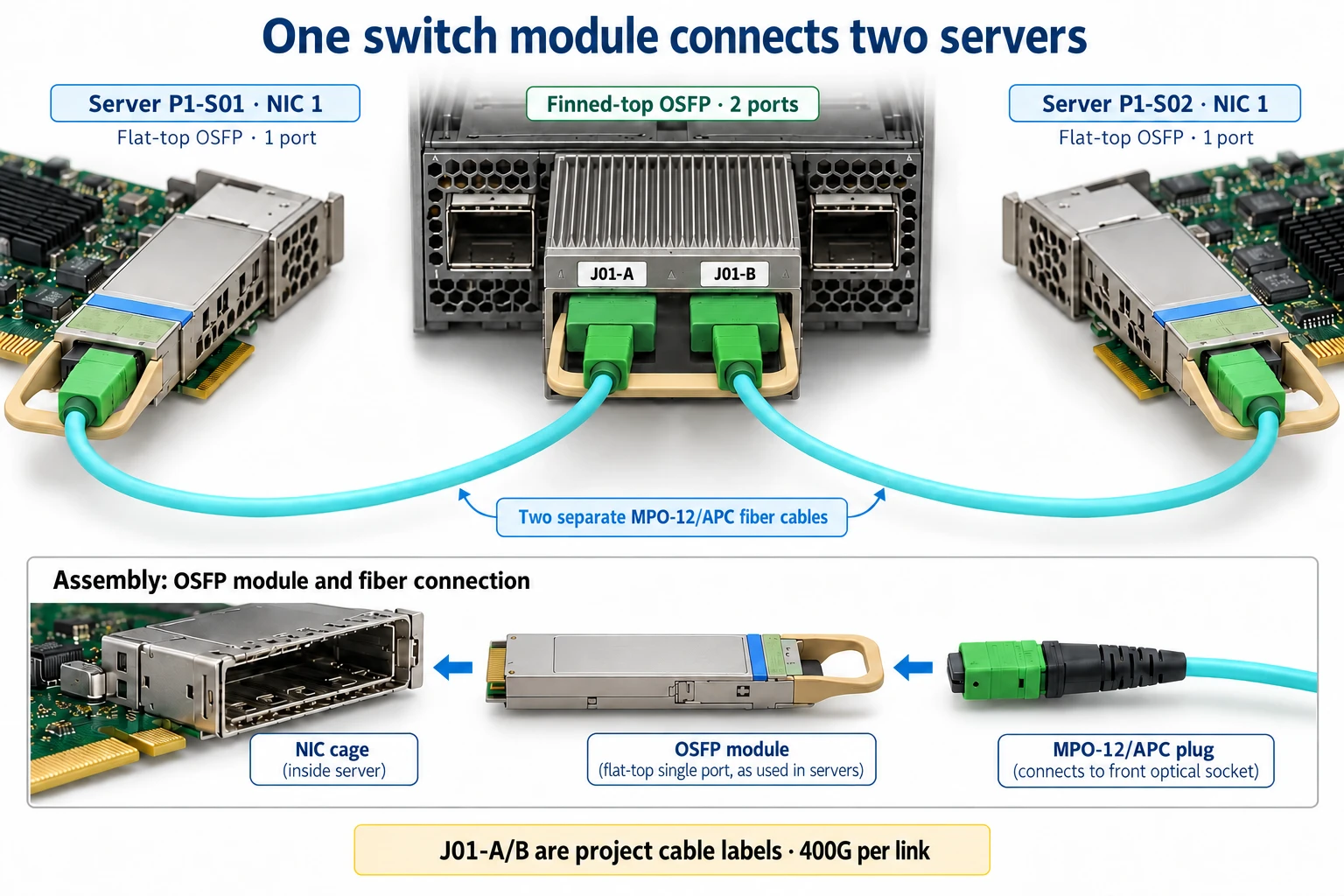
Matching components assembled together; each fiber cable independently connects one 400G port. Click to view the original image.
The first connection can now be traced by hand: a single-port optic in P1-S01 NIC1, one matching fiber, and one connector on a dual-port optic in P1-L01. The other half serves another server. Server-side optics are flat-top single-port modules; switch-side optics are finned dual-port modules, matched to their respective equipment.
“One module” is still too vague to hand over. I label cages J01 through J32 and their two connectors A and B, with the integrator mapping them to manufacturer numbers and software port names. J01-A on paper, its physical label, and a software query must identify one endpoint.
Before insertion, check both modules and the fiber model, inspect and clean end faces according to the manufacturer, then insert in the correct orientation and confirm locking. Connector and polarity must match as a set. Store slack in the designated cable-management space and maintain the specified bend radius, leaving access for maintenance.
Repeat the first connection across a cabinet and a pod
Only after the first connection is defined do I replicate it. Two servers per cabinet means 16 training outlets. Give each machine its own identifier, then expand the rule so growing quantities still lead back to a specific server.
The 640 servers form five pods of 128. Each pod has four 32-server access sections, with eight leaves per section. In P1's first section, NIC1 from all 32 servers goes to P1-L01, NIC2 to P1-L02, through NIC8. The next section uses L09 through L16. Four sections produce 32 leaves, with a defined destination for every outlet.
Pod: In this plan, a group of 128 training servers and two local switch layers.
Leaf: A lower switch that connects directly to servers.
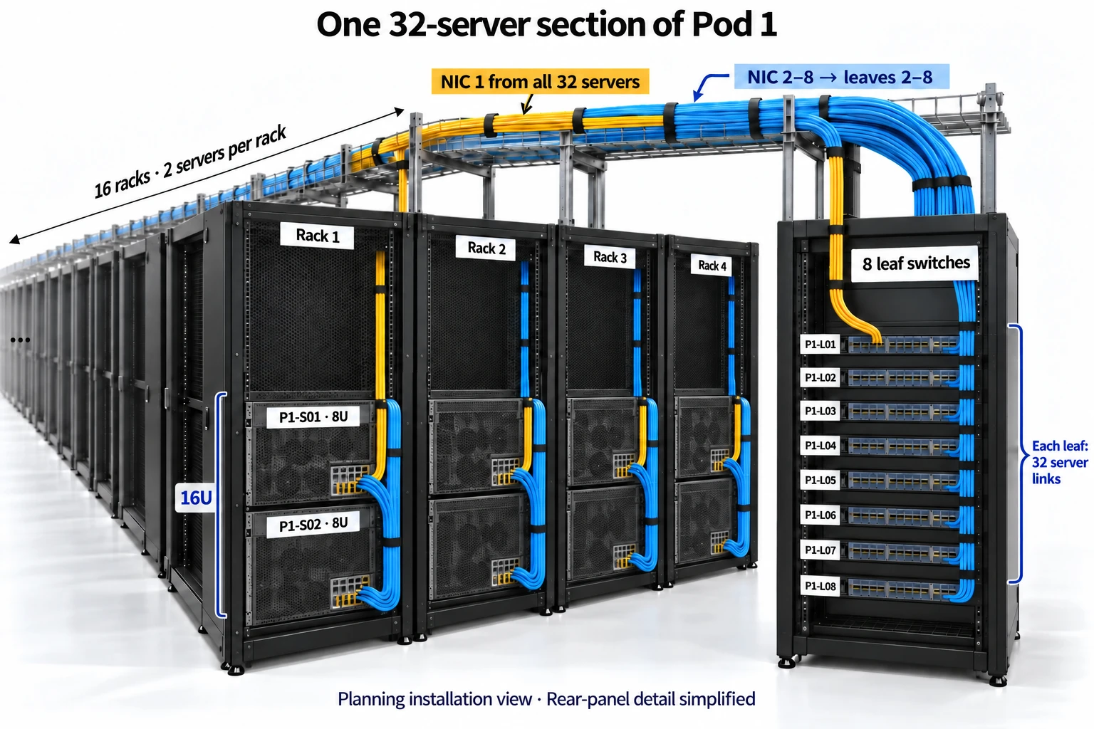
This illustration shows one 32-server access section, one quarter of a pod. Rear-panel details are simplified. Click to open the full image.
Follow the NIC1 route and count 32 server fibers entering one leaf. Two fit each dual-port module, so J01 through J16 are sufficient. The first checkable records look like this:
| Cable ID | Server endpoint | Leaf endpoint |
|---|---|---|
| P1-S01-N1 | P1-S01 NIC1 | P1-L01 J01-A |
| P1-S02-N1 | P1-S02 NIC1 | P1-L01 J01-B |
| P1-S03-N1 | P1-S03 NIC1 | P1-L01 J02-A |
| P1-S32-N1 | P1-S32 NIC1 | P1-L01 J16-B |
| P1-S01-N2 | P1-S01 NIC2 | P1-L02 J01-A |
Expanding this small table across five pods produces 160 leaves and 5,120 access links. The 20 spares have eight NICs each and reuse the original position's wiring during replacement. Thus procurement includes 660 × 8 = 5,280 NICs, while normal training uses 640 × 8 = 5,120 ports. Purchased spares and active connections now have separate counts.
Add aggregation, then connect five pods through the core
The servers are connected, but machines on different leaves still lack a path. The remaining sixteen dual-port modules on each leaf provide 32 outlets, one to each local aggregation switch A01 through A32. The 128 servers can now reach one another within their pod.
Aggregation switch: The middle layer in this plan, connecting a pod's leaves and sending traffic toward the core.
Continue upward to reach other pods. The core has 32 groups of three switches, 96 total. Aggregation switch seven connects only to C07-1, C07-2, and C07-3, distributing its 32 uplinks as 11, 11, and 10. Repeat that rule for the other groups.
Core switch: The upper layer connecting different pods in this three-layer design.
Three comes from the port count: five pods bring 32 uplinks each, so one core group needs 160 endpoints. Three 64-port switches use 55, 55, and 50 ports. The connections fit, and every pod receives the same share.
Cable positions: J cages, A/B connectors, and core port assignments
To locate an individual cable, expand the cage labels. P1-L01 J17-A goes to A01, J17-B to A02, through J32-B to A32. Aggregation's first 32 ports return to L01 through L32. Thus the L01-to-A07 connection joins L01 J20-A and A07 J01-A.
The core must also account for reach. Pods 1 and 2 in Hall A and pods 3 and 4 in Hall B are remote; pod 5 in Hall C is local. Place remote ports first and local ports afterward so both halves of each module use the same reach type. A 55-port core has 44 remote then 11 local ports; a 50-port core has 40 then 10.
| Cable ID | Planned endpoint A | Planned endpoint B |
|---|---|---|
| P1-L01-A07 | P1-L01 J20-A | P1-A07 J01-A |
| P1-A07-C07-1-01 | P1-A07 J17-A | C07-1 J01-A |
| P1-A07-C07-2-01 | P1-A07 J22-B | C07-2 J01-A |
| P1-A07-C07-3-01 | P1-A07 J28-A | C07-3 J01-A |
| P5-A07-C07-1-01 | P5-A07 J17-A | C07-1 J23-A |
The last row comes from local pod 5, so it follows the core's 44 remote ports. Map all project labels to manufacturer port names, then check them in management software. Routing must also match the parallel links between layers. NVIDIA's network-management documentation covers these topologies; the supplier uses it to implement routing and full-scale acceptance.
Count cables after ports: server-to-leaf, leaf-to-aggregation, and aggregation-to-core each have 5,120, totaling 15,360. Their 160 leaves, 160 aggregation switches, and 96 core switches total 416. These totals can now check the procurement list in reverse. Omitting a tier immediately breaks the count.
Why do we need 12,832 dual-port modules?
Round modules up on each actual device. Leaf and aggregation switches use all 64 ports. Each core group's 55, 55, and 50 ports require 28, 28, and 25 modules: 81 per group, or 2,592. Add 10,240 in the first two tiers for 12,832. Sixty-four half-ports remain empty, but procurement cannot remove half a module.
Use different parts inside a hall and between halls
The counts match, but distance raises another question. The server-to-leaf multimode combination reaches 50 meters with OM4 or 30 with OM3, selected using the official compatibility information. Measure the actual optical route, including tray rises, bends, patching, and slack, rather than the straight line between racks.
Between Halls A or B and Hall C, the candidate becomes NVIDIA's MMS4X00-NM dual-400G single-mode module. Its official reach is 500 meters including the specified two patch panels. Confirm both ends, single-mode fiber, connectors, and polarity together. The operator checks actual length and loss, redesigning routes outside the supported limits.
The four remote pods have 4,096 cross-hall links. Dual-port modules at both ends total 4,096 long-reach modules. The remaining 8,736 short-reach dual-port optics and 5,120 server single-port optics serve 11,264 within-hall links. Measure these too: a local route beyond multimode limits also moves to long-reach parts, with the parts list updated accordingly.
| Component | Planned quantity | Selection and delivery requirement |
|---|---|---|
| ConnectX-7 training NIC | 5,280, included in the 660-server configuration | Specify the part number and verify slots, PCIe paths, and complete-system tests |
| MQM9700-NS2F switch | 416 | 160 leaf, 160 aggregation, 96 core |
| MMA4Z00-NS400 server single-port optic | 5,120 | Flat-top single-port type at the NIC |
| MMA4Z00-NS short-reach dual-port optic | 8,736 | Switch-side type, matched to actual route length |
| MMS4X00-NM long-reach dual-port optic | 4,096 | Cross-hall switch-to-switch candidate; verify compatible pairs |
| Within-hall fiber link | 11,264 | Select actual length and compatible optical parts |
| Cross-hall single-mode fiber link | 4,096 | Include patch panels, loss, polarity, and maintenance slack |
Once the parts match, orientation returns us to the hot and cold aisles. MQM9700-NS2F intake is on the power side, exhaust on the optical side. Power faces cold air, optics face the hot aisle. Cable management and maintenance access follow that direction; wiring convenience cannot reverse the airflow.
Two server batches follow Part 3's placement list, with shared core and storage ready for first-batch integration. Test arrived machines and paths first, then complete the same schedule with batch two. Management and storage use separate networks; training ports have already been assigned individually.
Finally, compare hardware and software. On site, check machine, NIC slot, module, port, and cable ID. In software, check all eight cards, links, speed, and error indicators. NVIDIA link validation and topology comparison connect the installation to its records. Expand tests from two servers to a pod, across pods, then the full cluster, measuring effective bandwidth and recovery.
How Will the Next Engineer Reconnect This Cable?
The next engineer needs more than an overview. For the original P1-S01 NIC1-to-P1-L01 J01-A link, four connected records identify the card, prepare parts, locate endpoints, and establish verification. Asset labels show positions now; real slots, serial numbers, and results are entered after delivery.
| Document | Question it answers | How this connection appears |
|---|---|---|
| NIC and slot register | Which physical card is NIC1? | P1-S01, NIC1, specified part number, and actual slot/serial fields to complete |
| Optical parts and fiber list | Which parts must be ready? | One server single-port optic, half A of a leaf dual-port optic, and the matching fiber |
| Cable endpoint schedule | Where is the other end? | P1-S01 NIC1 → P1-L01 J01-A, with manufacturer and software port names added |
| Acceptance record | Who checked it, and what happened? | Endpoint photographs, module IDs, measured speed, errors, and communication-test logs |
The English PDF expands these four records and the aggregation-to-core links between halls. Planned 400Gb/s link rate and measured training throughput occupy separate fields because they describe different things. The full handover uses the same format for all 15,360 links.
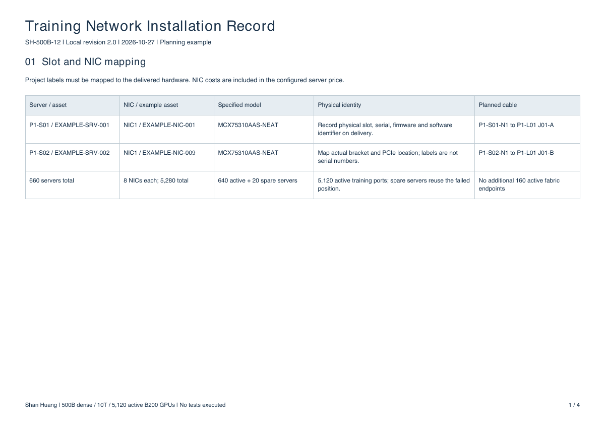
Training Network Installation Record
4-page PDF · Slots, components, cabling, and acceptance
Back behind the cabinet, a NIC label now leads through its module and fiber to a switch port. A replacement can be connected to the same location. The GPUs finally have routes for exchanging results. Another route needs attention next: where does training material arrive continuously, and where does progress get saved? That requires its own storage and data-delivery arrangement.
New ideas, straight to your inbox.
AI, engineering, and experiments. One or two useful emails a month.
No spam. Unsubscribe anytime.