
[Training a 500B LLM from Scratch] 11/25: How Do We Prepare a Data Center for These GPUs?
In Part 10, the supplementary training material passed through production, selection, and acceptance. Yet having the material ready does not start training. The GPUs on the purchase list first need somewhere they can keep working: enough space, enough power, and a way to remove the heat.
I reopen the equipment list from Part 3. There are 640 training servers and 20 spares, 660 in total. One looks like a chassis. Multiply it out, and finding a home for them becomes an engineering project of its own.
The facility plan still uses Flexential's Atlanta-Douglasville 2 in Georgia as its design and quotation target. First, draw the requirement: three 4.5 MW halls on one campus, providing 13.5 MW of IT capacity. At two servers per rack, 660 servers need 330 compute racks. To make this arrangement work, placement, power, and cooling must agree on the same drawing.
Why Is the Power in Two Halls Still Not Enough?
The first boundary is the campus. During training, 5,120 active GPUs exchange results frequently, so the main run stays on one campus, with dedicated links between the three halls. The next article follows the actual cross-hall fibers. For now, those connections must have a place in the facility plan.
The public Douglasville 2 information lists 36 MW of critical load and high-density rack capability. Its hall specification previously listed 4.5 MW and about 24,000 square feet, or 2,230 square meters, per hall. That gives the request three halls of a defined size, with capacity and area that a quotation can address. The delivery agreement fixes the actual hall numbers, floor plans, and access dates.
IT capacity: The power a facility can supply to servers, networking, storage, and other IT equipment. Cooling and other facility systems use additional power.
Why three halls? Add the servers first: at a planning figure of 14.5 kW each, 660 already require 9.57 MW. Two 4.5 MW halls provide only 9 MW, short of the servers alone, before networking and storage. Three leave room for the complete system and engineering headroom. The August 2026 official announcement still described the local 36 MW project as under construction. The 13.5 MW requirement therefore goes to the operator to establish capacity and delivery dates.
Almost all the electricity entering the equipment becomes heat that must leave again. In the drawing, yellow lines carry power through distribution equipment to the racks. Blue air passes through the servers; red heat returns to the cooling system. Both paths must work continuously.
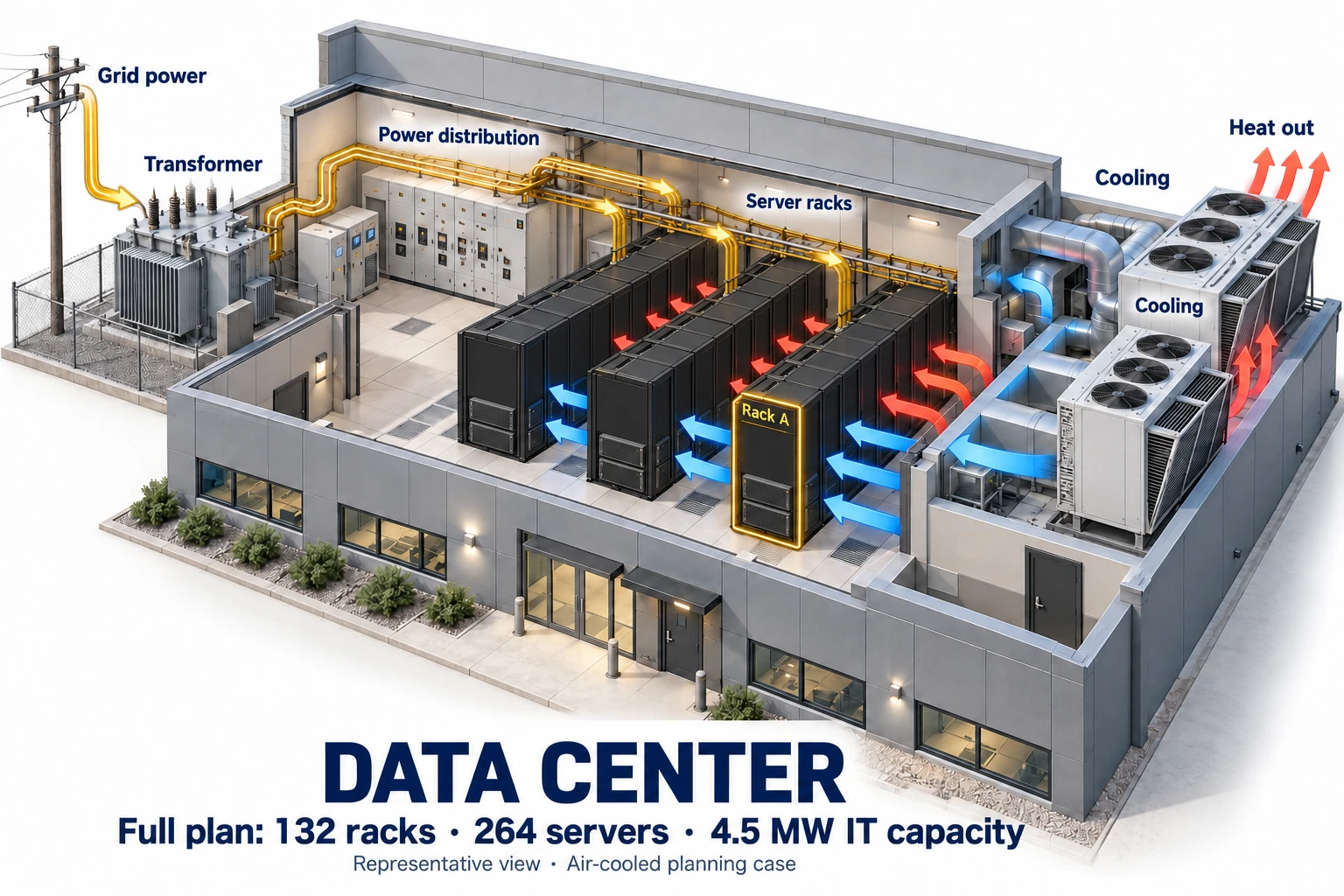
Click the image for the full-resolution version.
The second delivery needs a place before the first arrives. Otherwise, the early machines can be installed while the later ones lack contiguous capacity. Set the full placement plan first, then install in batches. Now narrow the view to one rack, the smallest piece of this larger arrangement.
Two Servers in One Rack: What Is the Remaining Space For?
The equipment determines what the rack must accommodate. The Exxact TS4-142487900 selected in Part 3 contains eight B200 GPUs in an 8U chassis, 930 mm deep. At about 35.6 cm tall, 8U is well beyond a desktop case.
U: A unit of rack equipment height. One U is approximately 4.45 cm.
I put the APC NetShelter AR3350B2 on the candidate list: 42U high, 750 mm wide, and 1,200 mm deep. Two servers occupy the lower 16U. Keeping heavy equipment low also helps installation and maintenance. Power and cables go at the rear, with blanking panels covering unused front openings.
Using only 16U of a 42U rack looks wasteful. Continue the calculation, though, and power or cooling can become the limit first. Two servers at 14.5 kW require 29 kW. Running at that power for an hour consumes about 29 kWh and leaves the corresponding heat for the facility to remove. Two servers per rack is this plan's density choice, giving us a manageable starting point for power, cooling, and maintenance.
Kilowatt (kW): A unit of power.
Kilowatt-hour (kWh): A unit of energy consumption. Running at 29 kW for one hour consumes 29 kWh.
The heat route is planned alongside the servers. The design uses air-cooled equipment with hot-aisle containment: cool air enters the front, passes through the servers, and leaves the rear into a return-air path. Blanking panels reduce hot air recirculating to the front. Each rack needs cooling for at least the planned 29 kW heat load, plus engineering headroom based on the final equipment requirements.
Hot aisle: The passage behind racks where hot exhaust air collects. Separating it from the cool intake side reduces mixing.
To turn the airflow drawing into installation conditions, the supplier must confirm the complete server's cooling requirements. Exxact's public page does not list all airflow, weight, and rail requirements. The procurement specification requests them so the rack and cooling design can be finalized together.
Open Rack A another level: two servers in the rack, and eight GPU modules inside one server. Facility, rack, server, GPU. The quantities on the purchase list now each have a physical location.
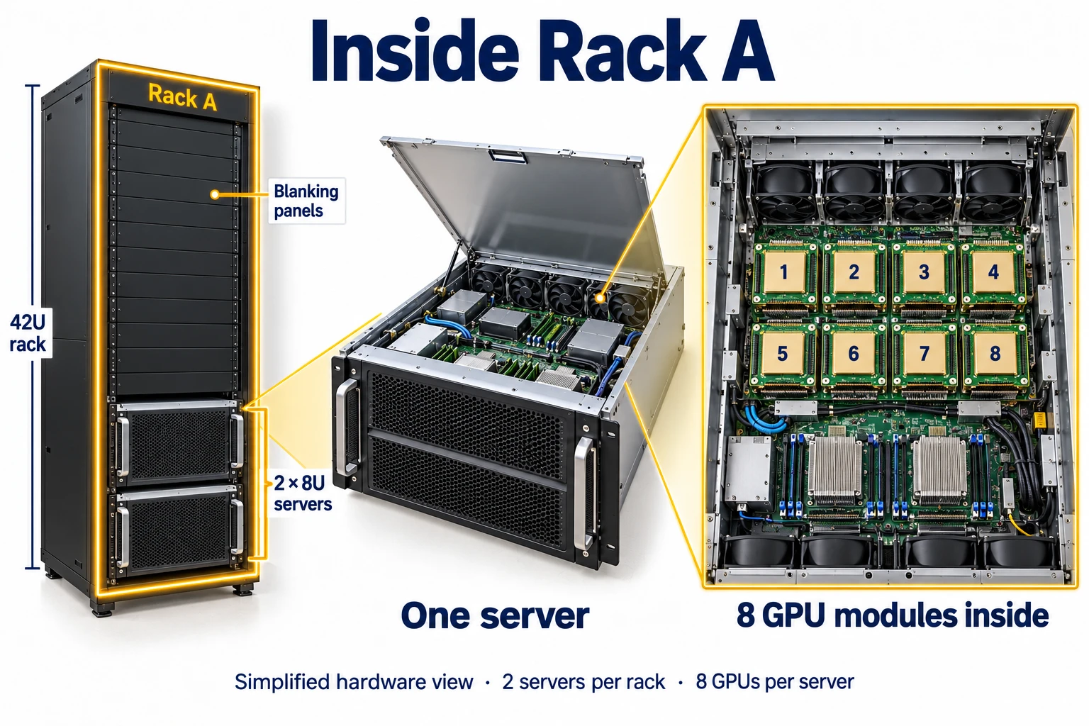
Click the image for the full-resolution version.
The drawing preserves the installation hierarchy and simplifies the internal layout.
Check where the power figure came from. On October 27, 2026, the Exxact configurator estimated 14,427 W with eight training NICs selected. The plan rounds that to 14.5 kW; the final electrical design uses the supplier-confirmed ordered configuration. Dimensions need the same scrutiny. A 1,200 mm cabinet does not automatically provide room for rails, plugs, and bent cables. Complete one trial rack installation, confirm placement, power, and airflow, then replicate it.
Which measurements do we check in the trial rack?
Start with space. APC lists the AR3350B2 at 1,991 mm high, 750 mm wide, and 1,200 mm deep, with a maximum mounting depth of 1,048 mm and a static load rating of 1,814.4 kg. The Exxact chassis is 930 mm deep, with rails, plugs, and cable bends needing additional space. The combined weight of the cabinet, two servers, power distribution, and cables must also be checked against the floor and the entire handling route.
Next, check the power paths. The configurator lists 12 power supplies with 6+6 redundancy. The supplier must provide a wiring diagram matching the facility's A/B feeds, including outlets, rated current, and server behavior after one feed fails. Supply ratings determine how the paths are designed; normal consumption follows the equipment load.
One Rack Fits. How Do We Place 330?
Once the trial rack is settled, the count can expand. The 660 servers occupy 330 racks: 320 for 640 training servers and 10 for 20 spares. The network divides the training servers into five pods of 128. I distribute those groups across the three halls, keeping the same grouping for the next article's wiring.
| Location | Training servers | Spares | Compute racks | Network and shared equipment |
|---|---|---|---|---|
| Hall A | 256 | 8 | 132 | Pods 1 and 2 with their switches |
| Hall B | 256 | 8 | 132 | Pods 3 and 4 with their switches |
| Hall C | 128 | 4 | 66 | Pod 5, shared core switches, and storage |
| Total | 640 | 20 | 330 | Five pods sharing one training network |
Pod: In this network design, a group of 128 training servers and its two local switching tiers.
A cabinet looks compact, but multiplying its footprint can conceal missing space. 330 × 0.75 m × 1.2 m = 297 square meters counts only cabinets. Maintenance and cooling aisles, network racks, installation staging, and facility equipment remain outside that figure. Place the 132, 132, and 66 racks and these areas on the operator's actual floor plan, then check doors, columns, floors, and cable routes.
Power follows the same equipment list. Deduct each item from the three halls' combined allowance:
| Use | Planned IT power |
|---|---|
| 660 servers, including training NICs | 660 × 14.5 kW = 9.57000 MW |
| 416 training switches | 416 × 1.720 kW = 0.71552 MW |
| Separate storage, management, and other IT equipment | 0.50000 MW allowance |
| Remaining design headroom | 2.71448 MW |
| Total | 13.50000 MW |
Avoid counting the same load twice. The switch figure uses the official maximum with active connections, so switch-side transceiver power is not added again. The 0.5 MW allowance becomes an equipment list once configurations are fixed. Redundant supplies add a backup path, rather than another normal operating load.
The total must fit, and each hall must fit separately. Halls A and B each contain 264 servers and 128 switches, requiring 4.04816 MW apiece. Hall C has 132 servers, 160 switches, and the 0.5 MW other-IT allowance, totaling 2.68920 MW. All three remain within 4.5 MW, giving the operator an equipment-based design to confirm for power and heat removal.
Megawatt (MW): A unit of power equal to 1,000 kW.
Another figure in the budget now needs its place: Part 3 uses a 10 MW operating load for electricity costs, while this plan reserves 13.5 MW. One estimates operation; the other provides available capacity. Actual energy follows meters and contract terms. Cooling and other facility consumption are accounted for through the applicable PUE.
Must Every Machine Arrive at Once?
With placement and capacity aligned, the delivery sequence can follow. The first batch has 330 servers, including 320 for training and 10 spares. The second matches it. Part 3 targets arrivals in months 4 and 6, with all three halls starting their leases in month 4 so later equipment retains contiguous space.
Splitting servers into two deliveries does not split every facility requirement in half. The first integration tests already need the shared core and storage, so those arrive earlier; full hall capacity is also reserved in the plan. Months 4 and 5 budget half the operating load for electricity, replaced later by site records. Rent and supporting infrastructure follow their respective contracts.
Installation testing grows from the smallest unit. First check one server's GPUs, NICs, and power. Then run both servers in a rack together and watch circuits, temperatures, and alarms. Expand to other racks after they pass, then test cross-hall communication, sustained data delivery, and recovery. The second batch joins the same placement plan, followed by full-scale acceptance with all 640 training servers.
Redundancy: Extra capability or paths provided for failures, such as feed B carrying the agreed load when feed A fails.
The Lights Are On. Can the Machines Train Together?
Illuminated servers are not yet ready to hand to the training team. I want records that establish they can work together. Acceptance therefore has five levels, each with a way to judge success:
| Acceptance level | How to judge it |
|---|---|
| One server | Model and serial number match the list; all eight B200s are recognized; memory and storage match; supplier health checks pass |
| One two-server rack | Both run the agreed load; circuits remain within design limits; intake and component temperatures meet supplier requirements; no thermal throttling or abnormal alarms are recorded |
| First delivery | All 2,560 GPUs in 320 training servers participate; network and storage meet contractual baselines; spare replacement is verified |
| Complete three-hall installation | All 5,120 GPUs in 640 servers participate; communication and data delivery meet agreed baselines; monitoring and alarm records are complete |
| Failure and recovery | The facility performs the approved power-transfer procedure; a training trial resumes from saved progress with results matching the test plan |
“Pass” still needs numbers. Procurement and integration contracts set temperature and performance thresholds for this equipment, and the test sheets include them before delivery. A failure can then be traced to an item, circuit, or service, repaired, and tested again in the same way.
The sequence also aligns with NVIDIA's DGX B200 guide, which places health and load checks before use. Our tools come from the Exxact supplier, while records accumulate from server to rack, first delivery, and full cluster.
The 660 machines now have a complete home in the plan: three halls on one campus, 13.5 MW, 330 two-server racks, and two installation batches, with power, airflow, and collaboration tested together. One thing remains on the drawing. The gold lines between racks are still strokes on a page. Next, we move behind the machines and turn them into NICs, modules, fibers, and a connection schedule that can be checked cable by cable.
New ideas, straight to your inbox.
AI, engineering, and experiments. One or two useful emails a month.
No spam. Unsubscribe anytime.